
CSDD & Exclusion Assessment
This guide covers the Cyber Security Design Description — the mandatory technical document submitted for Class approval — and the risk-based process for excluding systems from E26 scope.
1. Assembling the CSDD (The Submission File)
The CSDD is your vessel’s “Master Blueprint.” It proves to the Auditor that you have Identified your assets correctly. Your CSDD must include these three core pillars:
Must show physical cabling (Ethernet/Serial) and logical zones. Highlight all “Conduits” crossing between IT and OT environments.
Comprehensive list including firmware versions. All software must be cross-referenced against the Vulnerability Feed.
Identify critical protocols (Modbus, NMEA, S7). This matrix defines the “Blast Radius” in the event of a cyber incident.
1.1 CSDD Checklist for Class Submission
Before submitting your technical file to the Class Society, verify that these specific data points are documented to avoid RFI (Request for Information) delays.
| [ ] | Boundary Logic | Are all Firewalls/Diodes identified by physical location and port mapping? |
| [ ] | Dependency Impact | Does the CSDD list the ‘System Criticality’ for every asset found in the inventory? |
| [ ] | Vendor Data Flow | Are NMEA/Modbus/Proprietary flows mapped between different OEM systems? |
| [ ] | Software Baseline | Is there a ‘Frozen’ firmware version listed for all Category II & III components? |
Universal CSDD Index (IACS UR E26 Compliant)
This index fulfills the Cyber Security Design Description requirements for all major Classification Societies. Use it to organise technical evidence for the design and construction phase.
| Item | E26 Reference | Status |
|---|---|---|
| 1 — System & Zonal Architecture | ||
| 1.1 Security Zone & Profile Allocation | §4.2.1 | E26 Mandatory |
| 1.2 System Supplier & Functional Data | — | Best Practice |
| 1.3 Physical Access & Asset Locations | — | Best Practice |
| 2 — Connectivity & Data Flows | ||
| 2.1 Intra-Zone Communication Matrix | — | Best Practice |
| 2.2 Boundary Device & Firewall Rules | §4.2.1 | E26 Mandatory |
| 2.3 Untrusted Network Interfaces | §4.2.6 | E26 Mandatory |
| 3 — Technical Safeguards | ||
| 3.1 Malicious Code Protection (AV/EDR) | §4.2.3 | E26 Mandatory |
| 3.2 Access Control Documentation | §4.2.4 | E26 Mandatory |
| 3.3 Wireless Security Implementation | §4.2.5 | E26 Mandatory |
| 3.4 Remote Access Control (RAG) | §4.2.6 | E26 Mandatory |
| 3.5 Mobile & Portable Device Policy | §4.2.7 | E26 Mandatory |
| 4 — Operational Resilience & Recovery | ||
| 4.1 Incident Response Plan | §4.4.1 | E26 Mandatory |
| 4.2 Local & Manual Operation Procedures | §4.4.2 | E26 Mandatory |
| 4.3 Network Isolation Procedures | §4.4.3 | E26 Mandatory |
| 4.4 Fallback to Minimal Risk Condition | §4.4.4 | E26 Mandatory |
| 4.5 Recovery Plan | §4.5.1 | E26 Mandatory |
| 4.6 Controlled Shutdown, Reset & Restore | §4.5.3 | E26 Mandatory |
| 4.7 Recovery Manual References | — | Best Practice |
| 5 — Evidence & Certification | ||
| 5.1 Type Approval (TAC) Certificates | — | Best Practice |
| 5.2 Supplier UR E27 Compliance Docs | — | Best Practice |
| 5.3 Technical Justifications | — | Best Practice |
| 6 — System Exclusions | ||
| 6.1 Excluded System Registry | §6 | E26 Mandatory |
| 6.2 Negligible Risk RA Evidence | §6 | E26 Mandatory |
| 6.3 Final Class Review Justification | — | Best Practice |
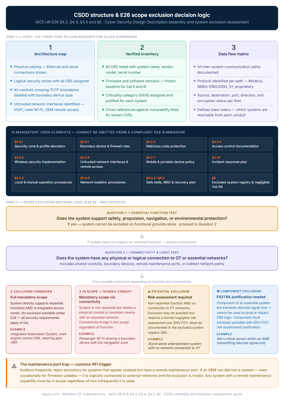
The diagram shows both the CSDD assembly structure and the exclusion decision logic in a single reference. They are presented together because the exclusion assessment is not a separate document — it is Section 6 of the CSDD, and the two-question logic gate shown here is what Class surveyors use to evaluate whether an exclusion claim is valid.
The maintenance port trap at the bottom of the diagram is worth particular attention. It is the most common reason a well-prepared exclusion register fails survey. A system that appears completely isolated often has a remote maintenance capability that an OEM uses once a year for firmware updates — and that single capability makes it logically connected to external networks. If that connection is not documented and assessed, the exclusion is invalid regardless of how isolated the system appears in normal operation.
<< Click the diagram to expand at full resolution
2. Scope Exclusion Logic (DNV F011/F021 & UR E26)
Use this decision matrix to determine if a system or component can be excluded from mandatory security requirements. Per DNV F011, any proposed exclusion must be supported by a Risk Assessment demonstrating Negligible Risk.
| System / Component | Essential Function Test | Connectivity & Logic Test | Requirement Result |
|---|---|---|---|
| Stand-alone Entertainment | Does not support safety, propulsion, or environmental protection. | No physical or logical connection to any OT or Essential networks. |
POTENTIAL EXCLUSION Requires RA “Negligible Risk” Score |
| Passenger Wi-Fi (Hotel) | Non-essential function, but uses shared infrastructure. | Shares a physical conduit or boundary device with the Nav Zone. |
MANDATORY SCOPE In scope due to Shared Conduit |
| Non-Critical Sensor (in AMS) | Component of an Essential System (AMS). | Discrete signal only; cannot be used to pivot or impact the CBS logic. |
COMPONENT EXCLUSION F021 RA justification required |
| Integrated Control System | Directly supports Essential Functions (Propulsion/Safety). | Core CBS logic; integrated across multiple zones. |
FULL MANDATORY SCOPE Exclusion forbidden by UR E26 |
Strategic Intelligence: The “Maintenance Port” Trap
Auditors often reject exclusions for systems that appear isolated but have a “Remote Maintenance Port”. If an OEM can dial into a system, it is logically connected to the external world. Always audit the Physical Layer (Layer 1) before claiming Section 6 exclusion.
2.1. Risk-Based Exclusion Checklist
To qualify for exclusion under DNV-CG-0325 or UR E26 Section 6, you must provide evidence for the following five points:
- Logical Isolation: No IP-network communication. No remote access.
- Physical Control: System is in a locked, restricted area.
- Port Lockdown: No physical ports (USB/RJ45) accessible to unauthorized personnel.
- Non-Criticality: System is not needed for Propulsion, Steering, or Power.
- No Integration: The system is not an Integrated Control System (ICS).
Class Evidence Tip
DNV and other Class Societies require that any “Negligible Risk” claim be supported by a technical justification. You must prove the system has a minimized attack surface and no potential impact on safety functions.
Compliance Documentation Previews
Standardized templates and technical logs. View watermarked previews below; All fillable forms and SOPs are free with a registered account.
The specific regulatory requirements this playbook satisfies. Use these references when preparing for Class survey or responding to a surveyor's checklist.