
Audit Evidence Templates
This playbook defines the complete documentation package required to satisfy the IDENTIFY phase of IACS UR E26 — covering the evidence artefacts a Class surveyor will request, how each document must be structured, and the most common reasons submissions generate an RFI (Request for Information) that delays approval.
Why Evidence Quality Matters
Class societies do not verify your security posture by inspecting systems — they verify it by reading your documentation. If your evidence package is incomplete, inconsistent, or missing required fields, the survey does not fail on the spot. Instead the surveyor issues an RFI, work stops, and your project schedule slips while you produce the missing documents under time pressure.
The most common RFI triggers for the IDENTIFY phase are not technical failures — they are documentation gaps. Systems that are correctly segmented still fail submission because the network diagram does not show conduit classifications, or because the CBS register lists systems without criticality categories. The architecture is fine; the evidence is not.
This playbook tells you exactly what to produce, what each document must contain, and what surveyors look for first.
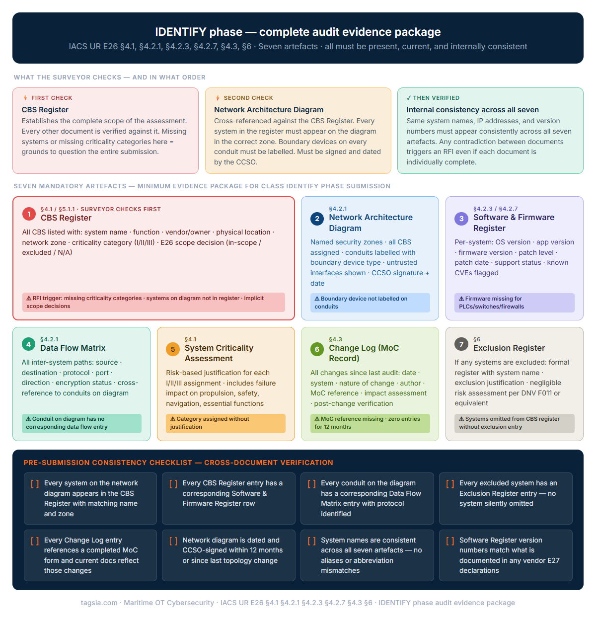
A Class surveyor reviewing an E26 IDENTIFY phase submission does not read every page sequentially — they start with the CBS Register, cross-reference it against the network diagram, then work through the other five artefacts looking for internal contradictions. A submission that has all seven documents but uses different system names in each one will generate RFIs even though all the information is technically present.
The diagram shows the seven artefacts, the E26 section each maps to, the most common RFI trigger for each, and the eight consistency checks that should be completed before any submission is sent to Class. The CBS Register is shown wider than the others because it is the anchor document — if the register is incomplete or inconsistent, no amount of quality in the other six documents will pass the submission.
<< Click the diagram to expand at full resolution.
1. The Complete IDENTIFY Evidence Package
The following seven artefacts make up the minimum required evidence package for the IDENTIFY phase. Each maps to a specific E26 requirement. All must be present, current, and internally consistent — meaning the same systems, IP addresses, and version numbers must appear across all documents without contradiction.
2. CBS Register — What Surveyors Check First
The CBS register is almost always the first document a Class surveyor reviews. It establishes the scope of the entire assessment — every other document is verified against it. If your network diagram shows a system that is not in the register, or if the register lists a system with no criticality category, the surveyor has grounds to question the completeness of the entire submission.
Each entry in the CBS register must include:
System name, manufacturer, model number, serial number (where applicable), and the vessel location (bridge, ECR, engine room, etc.)
Whether the system is vendor-supplied (within E27 scope) or owner/operator-supplied (outside E27 scope, full owner responsibility)
Category I (essential — propulsion, steering, safety), Category II (important — power management, navigation), or Category III (other — crew welfare, admin IT)
Which security zone the system belongs to, cross-referenced to the zone designations on the network architecture diagram
Whether the system has network connectivity, remote access capability, or is standalone/air-gapped. Standalone systems still require an entry — their isolation is itself a control.
Explicitly in scope, excluded (with reference to the Exclusion Register entry), or not applicable
Common RFI trigger: CBS registers that list system names without criticality categories, or that omit crew welfare and IT systems on the assumption they are “obviously out of scope.” Every system connected to the vessel network — directly or indirectly — must have an entry with an explicit scope decision. The surveyor cannot make that decision for you.
3. Network Architecture Diagram — What Must Be Shown
The network diagram is the visual proof of your zone and conduit model. E26 requires the diagram to show the security architecture — not simply a cable diagram. There is a meaningful difference. A cable diagram shows what is physically connected. A security architecture diagram shows what zones exist, what conduits cross between them, and what controls are in place at each boundary.
- IT network topology diagram showing IP addresses and switch ports
- Vendor-supplied single-system architecture diagram
- Physical cabling layout from the shipyard
- Diagram without zone boundaries marked
- Undated diagram with no revision history
- Named security zones with all CBS assigned to a zone
- Conduits shown as explicit connections between zones with boundary device type labelled
- Untrusted networks (internet, crew wifi, shore link) shown and clearly segregated
- Remote access entry points labelled
- Revision number, date, and CCSO signature block
The diagram does not need to be drawn in a specific tool. Visio, draw.io, and even a clean hand-drawn diagram scanned to PDF are all accepted. What matters is the information content, not the presentation format. The CCSO signature and date are mandatory — an unsigned diagram will generate an RFI regardless of content quality.
Common RFI trigger: Diagrams that show the network topology correctly but do not label conduit boundary devices (firewall, data diode, or DMZ). The surveyor needs to see what controls enforce the zone boundary — showing a line between two zones without identifying the boundary mechanism is not acceptable as evidence of segmentation.
4. Software & Firmware Register — The Most Commonly Incomplete Document
The software and firmware register is consistently the most incomplete document in audit packages. Most submissions have a CBS register and a network diagram in reasonable shape — but the software register either does not exist, covers only a subset of systems, or lists operating systems without firmware versions for embedded devices.
For every system in your CBS register, the software register must record:
Common RFI trigger: Registers that list OS versions for workstations but have no entries for managed switches, firewalls, PLCs, or SCADA servers — or that list “vendor responsible” for firmware without providing actual version numbers. The surveyor will ask: how can you assess whether a system is patched if you do not know what version it is running?
5. Change Log — Continuity Between Surveys
The change log is the document that proves your cyber security posture has been actively maintained between annual surveys — not just assembled for the audit. A surveyor seeing a change log with zero entries for the preceding 12 months will question whether changes occurred and were not documented, rather than assuming nothing changed.
Every change log entry must record:
- Date of change — when the work was carried out
- System affected — cross-referenced to the CBS register entry
- Nature of change — software update, configuration change, hardware replacement, new system, removal
- Change author — who made the change (ETO, vendor technician, etc.)
- MoC reference — the TAG-OT-MOC-01 form number authorising the change
- Impact assessment — brief statement on whether the change affected zone boundaries, conduits, or criticality classification
- Post-change verification — confirmation the system was tested after the change and the network diagram / software register were updated
Common RFI trigger: Change logs that exist but reference MoC forms that were never completed, or that record “firmware update performed” without specifying the version installed or post-change verification. The log entry and the MoC form must be consistent — surveyors cross-reference them.
6. Pre-Submission Consistency Check
Before submitting your evidence package, run through this consistency check. The most common reason a complete package still generates RFIs is internal contradictions between documents — the CBS register and the network diagram tell different stories about the same systems.
Vault Forms for This Playbook
Fillable templates for the evidence artefacts covered in this playbook. Free access with a registered account.
The specific regulatory requirements this playbook satisfies. Use these references when preparing for Class survey or responding to a surveyor's checklist.